
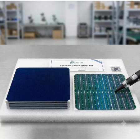
LONGi HPBC M10P0B Back Contact Solar Cell 182x91.875mm 4.4Wp
LONGi HPBC monocrystalline back contact solar cell, type M10P0B, half-cell format 91.875 x 182 mm and 165 µm thick. Fully black front with no busbars or metal grid: both polarities sit on the rear on 1.3 mm discontinuous soldering pads.
Conversion efficiency up to 26.4%, with a single-piece output between 4.17 and 4.40 Wp at STC. Power temperature coefficient -0.283 %/K.
A component intended for custom photovoltaic module manufacturing and for BIPV projects with high aesthetic requirements.
The LONGi HPBC M10P0B back contact solar cell is a monocrystalline silicon cell in half-cell format, 91.875 x 182 mm, obtained by cutting an M10 wafer in two. Its defining feature is the HPBC (Hybrid Passivated Back Contact) architecture: there is no metallisation whatsoever on the front, only the silicon nitride anti-reflective coating. Both contacts, positive and negative, are located on the rear. The result is a uniform collecting surface, aesthetically solid black, and a higher number of photons captured over the same area.
What back contact technology changes
In a conventional cell the grid of busbars and fingers on the front intercepts part of the light before it reaches the silicon: a structural optical loss that cannot be designed away. By moving all metallisation to the rear, back contact architecture recovers that surface. Hence the efficiency of up to 26.4% declared by LONGi for this series, against the 22-23% typical of PERC cells with front busbars still widely in use.
The second advantage is behaviour under partial shading: with the contacts on the rear the current path tolerates localised shadows better, and hot spot heating stays lower than in an equivalent front-contact architecture.
Read the rating carefully: full wafer or half cell?
This is the point where the arithmetic most often goes wrong, and it deserves to be said plainly. The official LONGi datasheet lists the electrical bins for the full 182 x 182 mm wafer (up to 8.79 W and 14.141 A), whereas the physical product is the piece already cut in half, measuring 91.875 x 182 mm.
On the single piece you receive, therefore, current is halved and voltage stays the same: roughly 4.17-4.40 Wp, Isc between 6.96 and 7.07 A, Uoc between 0.725 and 0.739 V. The geometry confirms it: 167.2 cm² of surface at 26.4% efficiency gives 4.41 W under 1000 W/m². Sizing a string on the 8.79 W figure from the table would overstate module power by a factor of two.
M10P0B technical specifications
| Technology | Monocrystalline back contact HPBC |
| Piece dimensions | 91.875 x 182 mm ±0.25 mm (R131.4 mm ±0.25 mm) |
| Thickness | 165 µm ±16.5 µm |
| Front side | Silicon nitride anti-reflective coating, no metallisation |
| Rear side | 1.3 mm discontinuous soldering pads, + and - polarities |
| Efficiency | 25.0% to 26.4% |
| Output per piece | 4.17 - 4.40 Wp |
| Open circuit voltage Uoc | 0.725 - 0.739 V |
| Voltage at MPP | 0.635 - 0.649 V |
| Short circuit current Isc | 6.96 - 7.07 A |
| Fill factor | 82.51% - 84.14% |
| Power temperature coefficient | -0.283 %/K |
| Voltage temperature coefficient | -0.23 %/K |
| Current temperature coefficient | +0.03 %/K |
| Shunt resistance | Rsh greater than or equal to 100 ohm |
| Reverse current Irev2 | Below 10 A |
| Measurement conditions | STC: 1000 W/m², AM1.5, 25 °C |
Current and power values refer to the cut piece; voltage and fill factor are identical to those of the full wafer.
Performance in diffuse light
The datasheet documents how the cell behaves as irradiance falls. Current follows light intensity linearly, while open circuit voltage stays remarkably high even under overcast skies: at 200 W/m², one fifth of full irradiance, Uoc still holds 94.6% of its nominal value.
| Irradiance | Relative Isc | Relative Uoc |
| 1000 W/m² | 1.000 | 1.000 |
| 800 W/m² | 0.800 | 0.994 |
| 600 W/m² | 0.600 | 0.985 |
| 400 W/m² | 0.400 | 0.972 |
| 200 W/m² | 0.200 | 0.946 |
In practice this means a module built from these cells reaches the inverter start-up voltage early in the morning and holds it until late, grey days included.
What it is for, and how it is interconnected
This cell is an industrial semi-finished component, not something to assemble with ribbon and a soldering iron. It needs saying without hedging: because both polarities sit on the rear on 1.3 mm discontinuous pads, interconnection calls for a conductive backsheet or a patterned ribbon aligned to those pads, not the classic front-to-rear stringing used on busbar cells. Anyone looking for cells for a hand-soldered DIY panel will be better served by the conventional 3BB or 5BB monocrystalline cells already in our catalogue.
The proper applications for this cell are:
- Manufacturing of custom photovoltaic modules with high efficiency, where maximum power per square metre matters
- BIPV and architectural photovoltaics, where a uniform black front with no metal grid is an aesthetic requirement
- Compact modules for special applications: marine, street furniture, signage, own-brand products
- Research, laboratory and training work on back contact architectures
- Spare parts and repair of existing back contact modules
MR WATT designs and manufactures custom photovoltaic modules: if what you need is a finished module built from these cells rather than the bare cell, we can handle lamination and interconnection starting from the dimensions and power output you require.
Frequently asked questions
How many watts does a single LONGi HPBC M10P0B cell actually produce?
The 91.875 x 182 mm piece produces between 4.17 and 4.40 Wp at STC, depending on the efficiency bin (25.0% to 26.4%). The 8.33 to 8.79 W figures shown on the LONGi datasheet refer to the full 182 x 182 mm wafer before cutting: on the cut piece the current is halved while the voltage stays the same.
Can I solder this cell with ribbon and an iron like ordinary cells?
No, and it is worth knowing before you buy. There is nothing to solder on the front, and on the rear the two polarities sit on 1.3 mm discontinuous pads that must be reached with a conductive backsheet or an aligned patterned ribbon. For manual DIY assembly with ribbon and solder, monocrystalline cells with front busbars are the better choice.
How many cells do I need to build a 400 W module?
At an average 4.3 Wp per cell you need roughly 93 pieces gross. In practice you design around an even, tidy number, typically 96 or 108 cells, allowing for the few percentage points lost in encapsulation compared with the sum of the bare cells. With 108 cells at 4.3 Wp you land on a module in the 445-460 W range.
How does LONGi HPBC differ from SunPower back contact cells?
Both move the contacts to the rear and eliminate shading from a front grid, but they differ in process and format. LONGi HPBC combines passivation with back contact architecture on the large-area M10 format, designed for volume module production. The SunPower cells available in our catalogue come in smaller 125x125 mm and 166x166 mm formats, easier to handle in compact projects and DIY builds.
Does the cell lose much power when the module heats up in summer?
The power temperature coefficient is -0.283 %/K. With a cell reaching 65 °C at midday in summer, 40 K above the 25 °C reference, the loss is about 11.3%: a 4.4 Wp cell delivers roughly 3.9 W at that moment. That is in line with the best monocrystalline cells on the market and better than older polycrystalline cells, which comfortably exceed 0.4 %/K.